The basic idea is that I'd use a distance sensor to spot people walking up the sidewalk to my house and slowly dim the lights as they get closer and closer. When they're standing there at the door, I wanted them to be surrounded by almost-darkness with the white christmas lights flickering dimly while I handed out candy.
To achieve this effect, I knew I'd need a reliable distance sensor that could spot a humanoid/child up to 20 feet away and then I'd need some way to control lights running off of AC current.
I sought out the MaxBotics MaxSonar EZ-1 board to handle the distance sensing (http://www.maxbotix.com/MaxSonar-EZ1__FAQ.html). It's a clever single-board controller for a 40kHz ultrasonic transducer. It uses a single-transducer model rather than the two-sensor style of Devantech's. I've never used a Devantech sensor, but the MaxBotics model fit my budget and was carried by SparkFun, so I ordered it up.
The controller board supports three different output formats for distance sensing information: Serial, PWM, and analog. I chose to use the analog output and the ATmega8's built-in ADC to get my distance information.

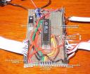
Here are the subsystems, labelled for your protection.

Here's the outlet box I built. With the help of the guy at Pini's Hardware here in town, I got it up to building code as well as getting it functional. It's four separate lines on the four outlets.
There was something extremely satisfying about labeling the outlets "BIT 0" and "BIT1" and so on. They were just bits on one of the ATmega8's output ports!

Outlet Box
For controlling the lights, I checked out some options out there for controlling house current from TTL that use triacs and optocouplers. One of the better ones I found was the SEMITONE "Open Dimmer" project. http://semitone.sourceforge.net/wiki/index.php/Main_Page
Rather than take chances on my first foray into house current, though, I opted to buy a pre-made board. One of my favorite electronics suppliers, Futurlec, had a great board they made themselves. It was cheap at $25.
http://www.futurlec.com/AC_Opto_Output_4.shtml
I doubted I could make one as cheaply and the construction seemed very solid and had just what I needed. It's driven by TTL signals and has two separate connectors for interfacing to your uC board. It's optically isolated, fuse-protected, and uses screw terminals for my AC lines. Perfect!

Relay Board
Here's a picture of the MaxBotics sonar range finder, on the left, and the 8 LED debugging output device on the right. I plug a ribbon cable with 8 SMD LED's with 1k SMD current limiting resistors wired to common ground with one LED per bit on PORTB of the ATmega8. I write to these bits to help debug things.

Here's a closeup of the transducer:

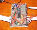
Here's the ATmega8 controller board I use for most of my projects. Click on it for the Really Big version.

And here it is again with ports labelled.

Because I got started late, I had to do the build in 2 days (actually two evenings, and one morning) and got it working Halloween morning at 9:45am--just in time to scoot off to work.
I think it was a big success. My Halloween guests were suitably baffled by the inexplicably dimming and flashing lights and it created a great atmosphere for handing out treats.
...and I didn't manage to burn the house down or sustain a filling-rattling electric shock in the process. Always a plus! ·
No comments:
Post a Comment