My dog is blind. Well, mostly blind---he can see a few feet and light and dark---but for most intents and purposes, he's blind. He's not blind in old age, but blind congenitally---he's only 3. His name is Lucky. As a golden retriever, he's obsessed with getting, keeping, carrying, fetching a ball shaped object of any sort. I set out to make a ball that beeps that he can find easily since his hearing is very acute now that he's been fully blind for a while.
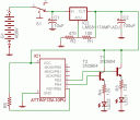
I scratched my original design for the Lucky Beepy Ball that was built around a LM556 timer chip and a handful of components (four resistors, two capacitors, and two signal transistors) as being a little too heavyweight for putting inside a ball. I did a lot of head scratching, reading, and doing other builds to learn more and finally settled on a very simple design: 1 ATtiny13V microcontroller, one piezo speaker, a small battery, and a switch. You can't get too much simpler than that.
The Atmel ATtiny13V was PERFECT for this job, as it had a low pin count (it's an 8 pin ATtiny) and operated well in a wide range of voltages. It can operate normally at between 1.8v and 5.5v (the 'V' model of the ATtiny13 is the low voltage version) and is plenty fast (I run mine at 4.8MHz on the internal oscillator). Best of all, it can source and sink at least 20mA on its digital output pins, and has a nice 8 bit timer built in that is easy to program for interesting bleepy sounds.
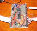
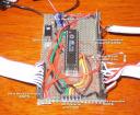
First I prototyped my design on a small piece of breadboard. All the ATtiny13V REALLY needs is the Vcc connection on pin 8, the GND connection on pin 4, and the two legs of the piezo speaker on pins 2 and 3, but I used the breadboard as my programming harness as well so you can see the 6 pin ISP header at the top. It took a little experimentation to get the beep sound the way I wanted it.
I wanted a beep sound that was easily audible by a dog under a lot of conditions. I figured a chirp would probably work the best. It would start at a high frequency above human hearing but dog-audible, and then decrease in frequency over time until it got low enough so that the wavelength was long enough to have good travel properties through tall grass. Long wavelength sound travels greater distances and can pass through solid objects better than short wavelength sound, so I wanted to take advantage of this property. I wanted alternating periods of chirping and silence so that it was easier for Lucky to triangulate the position of the sound. With a constant chirping, I was concerned that the sound reflection would interfere with his ability to locate the source.

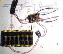
Here are the parts all laid out and ready to assemble. This build was going to be free-formed (point to point wiring) instead of boarded on a piece of experimenters board/veroboard since it needs to be compact and fit inside a ball or Kong ball of some kind.

After programming the ATtiny13V with my chirpy sound code, I ruthlessly hacked its legs off with a wire nipper. This was surprisingly painful for me to do... there's something about defacing a MCU that physically hurts. I wanted unused pins to be out of the way to reduce the possibility of a short and to keep them from interfering with other parts as I put everything together.

The battery I'm using is a 2.4v NiMH battery that I salvaged out of a tiny radio controlled car (one of those Hot Wheels-sized radio control cars that you dock with the transmitter to charge it.) I hadn't used the radio control car much before it broke, so I took it all apart and saved a few select pieces from it. This battery only stores 70mAh worth of charge, but then I don't anticipate that the ATtiny13V and the piezo are going to really need all that much. Plus it was the perfect size. I soldered right onto it at each end.

I brought the positive lead from the "bottom" of the battery up to the center pole on the SPDT switch so I can turn this thing off when we're done playing ball. I soldered the switch's metal housing directly to the negative side of the battery by using a little liquid solder flux (I have a solder flux pen I use for things like this) to get everything to stick.

Next, I mounted the ATtiny13V directly on the switch, soldering the Vcc pin (pin 8) directly to one side of the switch. Then I soldered the GND pin (pin 4) directly to the metal housing. Pins 2 and 3 that you can see in the right hand picture are going to be wired up to the piezo speaker.

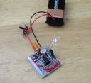
Here the speaker is wired to the MCU and the wiring is done.

Now it's time to hot glue this mess to make it more shock resistant and to keep everything in place. I'm using a typical craft hot glue gun to turn this all into a big capsule shaped insert that I can put inside a "Kong" brand dog toy to play fetch with.

... to be continued ...


