Tuesday, December 4, 2007

Lucky's Beepy Ball II!

UPDATE! Scroll to the bottom to see the results of the first trial run!

My dog is blind. Well, mostly blind---he can see a few feet and light and dark---but for most intents and purposes, he's blind. He's not blind in old age, but blind congenitally---he's only 3. His name is Lucky. As a golden retriever, he's obsessed with getting, keeping, carrying, fetching a ball shaped object of any sort. I set out to make a ball that beeps that he can find easily since his hearing is very acute now that he's been fully blind for a while.

I scratched my original design for the Lucky Beepy Ball that was built around a LM556 timer chip and a handful of components (four resistors, two capacitors, and two signal transistors) as being a little too heavyweight for putting inside a ball. I did a lot of head scratching, reading, and doing other builds to learn more and finally settled on a very simple design: 1 ATtiny13V microcontroller, one piezo speaker, a small battery, and a switch. You can't get too much simpler than that.

The Atmel ATtiny13V was PERFECT for this job, as it had a low pin count (it's an 8 pin ATtiny) and operated well in a wide range of voltages. It can operate normally at between 1.8v and 5.5v (the 'V' model of the ATtiny13 is the low voltage version) and is plenty fast (I run mine at 4.8MHz on the internal oscillator). Best of all, it can source and sink at least 20mA on its digital output pins, and has a nice 8 bit timer built in that is easy to program for interesting bleepy sounds.

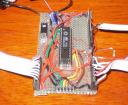
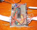
First I prototyped my design on a small piece of breadboard. All the ATtiny13V REALLY needs is the Vcc connection on pin 8, the GND connection on pin 4, and the two legs of the piezo speaker on pins 2 and 3, but I used the breadboard as my programming harness as well so you can see the 6 pin ISP header at the top. It took a little experimentation to get the beep sound the way I wanted it.

I wanted a beep sound that was easily audible by a dog under a lot of conditions. I figured a chirp would probably work the best. It would start at a high frequency above human hearing but dog-audible, and then decrease in frequency over time until it got low enough so that the wavelength was long enough to have good travel properties through tall grass. Long wavelength sound travels greater distances and can pass through solid objects better than short wavelength sound, so I wanted to take advantage of this property. I wanted alternating periods of chirping and silence so that it was easier for Lucky to triangulate the position of the sound. With a constant chirping, I was concerned that the sound reflection would interfere with his ability to locate the source.

20071126110347833_1_original.jpg

Here are the parts all laid out and ready to assemble. This build was going to be free-formed (point to point wiring) instead of boarded on a piece of experimenters board/veroboard since it needs to be compact and fit inside a ball or Kong ball of some kind.

20071126110347833_2_original.jpg

After programming the ATtiny13V with my chirpy sound code, I ruthlessly hacked its legs off with a wire nipper. This was surprisingly painful for me to do... there's something about defacing a MCU that physically hurts. I wanted unused pins to be out of the way to reduce the possibility of a short and to keep them from interfering with other parts as I put everything together.

20071126110347833_3_original.jpg

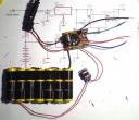
The battery I'm using is a 2.4v NiMH battery that I salvaged out of a tiny radio controlled car (one of those Hot Wheels-sized radio control cars that you dock with the transmitter to charge it.) I hadn't used the radio control car much before it broke, so I took it all apart and saved a few select pieces from it. This battery only stores 70mAh worth of charge, but then I don't anticipate that the ATtiny13V and the piezo are going to really need all that much. Plus it was the perfect size. I soldered right onto it at each end.

20071126110347833_4_original.jpg

I brought the positive lead from the "bottom" of the battery up to the center pole on the SPDT switch so I can turn this thing off when we're done playing ball. I soldered the switch's metal housing directly to the negative side of the battery by using a little liquid solder flux (I have a solder flux pen I use for things like this) to get everything to stick.

20071126110347833_5_original.jpg

Next, I mounted the ATtiny13V directly on the switch, soldering the Vcc pin (pin 8) directly to one side of the switch. Then I soldered the GND pin (pin 4) directly to the metal housing. Pins 2 and 3 that you can see in the right hand picture are going to be wired up to the piezo speaker.

20071126110347833_6_original.jpg

Here the speaker is wired to the MCU and the wiring is done.

20071126110347833_7_original.jpg

Now it's time to hot glue this mess to make it more shock resistant and to keep everything in place. I'm using a typical craft hot glue gun to turn this all into a big capsule shaped insert that I can put inside a "Kong" brand dog toy to play fetch with.

20071126110347833_8_original.jpg

... to be continued ...


Spooky Halloween Light Dimmer

Here's a quickie image gallery of my Halloween Door Light Dimmer system I cobbled together for a spooky Halloween gag.

The basic idea is that I'd use a distance sensor to spot people walking up the sidewalk to my house and slowly dim the lights as they get closer and closer. When they're standing there at the door, I wanted them to be surrounded by almost-darkness with the white christmas lights flickering dimly while I handed out candy.

To achieve this effect, I knew I'd need a reliable distance sensor that could spot a humanoid/child up to 20 feet away and then I'd need some way to control lights running off of AC current.

I sought out the MaxBotics MaxSonar EZ-1 board to handle the distance sensing (http://www.maxbotix.com/MaxSonar-EZ1__FAQ.html). It's a clever single-board controller for a 40kHz ultrasonic transducer. It uses a single-transducer model rather than the two-sensor style of Devantech's. I've never used a Devantech sensor, but the MaxBotics model fit my budget and was carried by SparkFun, so I ordered it up.

The controller board supports three different output formats for distance sensing information: Serial, PWM, and analog. I chose to use the analog output and the ATmega8's built-in ADC to get my distance information.

20071102102103855_1_original.jpg

Here are the subsystems, labelled for your protection.

20071102102103855_2_original.jpg

Here's the outlet box I built. With the help of the guy at Pini's Hardware here in town, I got it up to building code as well as getting it functional. It's four separate lines on the four outlets.

There was something extremely satisfying about labeling the outlets "BIT 0" and "BIT1" and so on. They were just bits on one of the ATmega8's output ports!

20071102102103855_3_original.jpg
Outlet Box

For controlling the lights, I checked out some options out there for controlling house current from TTL that use triacs and optocouplers. One of the better ones I found was the SEMITONE "Open Dimmer" project. http://semitone.sourceforge.net/wiki/index.php/Main_Page

Rather than take chances on my first foray into house current, though, I opted to buy a pre-made board. One of my favorite electronics suppliers, Futurlec, had a great board they made themselves. It was cheap at $25.

http://www.futurlec.com/AC_Opto_Output_4.shtml

I doubted I could make one as cheaply and the construction seemed very solid and had just what I needed. It's driven by TTL signals and has two separate connectors for interfacing to your uC board. It's optically isolated, fuse-protected, and uses screw terminals for my AC lines. Perfect!

20071102102103855_4_original.jpg


Relay Board

Here's a picture of the MaxBotics sonar range finder, on the left, and the 8 LED debugging output device on the right. I plug a ribbon cable with 8 SMD LED's with 1k SMD current limiting resistors wired to common ground with one LED per bit on PORTB of the ATmega8. I write to these bits to help debug things.

20071102102103855_5_original.jpg

Here's a closeup of the transducer:

20071102102103855_6_original.jpg

Here's the ATmega8 controller board I use for most of my projects. Click on it for the Really Big version.

20071102102103855_7_original.jpg

And here it is again with ports labelled.

20071102102103855_8_original.jpg

Because I got started late, I had to do the build in 2 days (actually two evenings, and one morning) and got it working Halloween morning at 9:45am--just in time to scoot off to work.

I think it was a big success. My Halloween guests were suitably baffled by the inexplicably dimming and flashing lights and it created a great atmosphere for handing out treats.

...and I didn't manage to burn the house down or sustain a filling-rattling electric shock in the process. Always a plus! ·

Pumpkinlight!

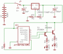
I put together a simple AVR-based device to stand in for the tried-and-true pumpkin candle this year. It uses two high-output (12,000 mcd) white LED's driven (a little too hard) by a regulated 5v supply that's shared with an ATtiny13v. All of this runs off of a 9v battery and should last for days given the tiny amount of current it draws.

The bill of materials isn't super long, and I had everything on hand so putting it together was pretty easy. I free-formed the first one, wrote the AVR Studio assembly code, then went back and made a proper schematic and built the second one. The first one is a lot uglier than the second due to all the rework and the extra wiring for the ISP connection.

C1 10uF
C2 100uF
G1 AB9V
IC1 ATTINY13V-10PU
IC2 LMS8117AMP-ADJ
LED1 High output white 5mm
LED2 High output white 5mm
R1 150
R2 470
R3 120
R4 120
R5 10k This is a 10k for a pull-up on the RESET pin
S1 Small SPDT sliding switch
T1 2N3904 Any small signal transistor will do
T2 2N3904 I used the 2N3904 because I have a big bag of them

Here are all of the materials required, assembled in marching order:

20071018173736317_1_original.jpg
Here's the schematic:

20071018173736317_2.gif

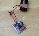
Here's the finished product (the second one... after I knew what I was doing. My layout still sucks, but it all fits and is fairly orderly.)

20071018173736317_3.jpg

Microchip PIC?

At home lately I’ve been trying to learn about electronics and simple analog circuits towards understanding microcontrollers from the bottom up rather than from the top down. In the past, I’ve relied on the kindness of others and/or good books or websites to handle all the component work and stuck to microcontroller programming in C. In C, microcontroller programming is just a bunch of bit operations, shifting, loops, polling, etc. But every time things failed to work like you think they would in “normal” programming (microprocessors) it invariably came down to the hardware, or the interface between the micro controller and the hardware---not the C language implementation or the code itself.

So in working from the electrons up, I’m finally to the point where I’m programming again now that I have a working knowledge of how resistors, capacitors, diodes, transistors, inductors and voltage regulators come into play. But the programming is in assembly, and my only previous assembly experience is on PowerPC architecture (some experience) and 680x0 architecture (a fair amount of experience a long long time ago.)

There are basically two ubiquitous chip families in simple 8 bit microcontroller programming. There are a lot more, but these two are far and away the most popular and often-used. They’re the PIC processors from Microchip and the AVR family from Atmel. The PIC’s seem the most popular overseas and the AVR’s seem most popular in the United states, though the AVR’s are (rightfully) starting to overtake PIC’s.

PIC is an abomination.

Here is a list of things I’ve come to loathe:

1. Program space is organized into 14-bit (yes, that’s FOURTEEN BIT) words.
2. There’s only one register, called W, and it only supports a tiny set of addressing modes.
3. Accessing data is done via the “file registers” which is just a fancy way of describing more 14-bit words in program space.
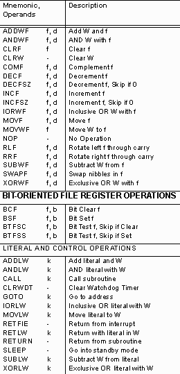
4. There are no conditional branches, you test condition codes as bit operations with the condition code register and there are only “skip the next instruction” kinds of branching.

I have to stop here and offer an example of how fucked up this is. You have to test the OPPOSITE case you want, with a operand that conditionally SKIPS the next instruction.

;
; I want to see if bit 4 is set in my file register
;
BTFSC SomeFileRegister, 4 ; so I test to see if the bit ISN’T set “Bit Test File and Skip if Clear”
GOTO _TheBitWasSetLabel
.
.
_TheBitWasntSetLabel:
; continue normal execution
.
.

[ elsewhere in the code ]

_TheBitWasSetLabel:
; the condition was met
.
.

Two instructions to do a conditional branch, and you have to test the INVERSE CASE.

Jesus.

What the hell were they thinking?

5. The same thing applies for loop counters, where you do the test at the decrement or increment instruction and SKIP the next statement (which is always a GOTO for conditional branches).
6. It’s an 8-bit architecture, so the working values are all 8 bit, but stored in 14 bit file registers (program memory.) That’s 6 bits wasted when storing data.
7. Storing a string in program space requires building a table of return-literal-value instructions, and then jumping the program counter to the appropriate line by adding to the PC file register. WTF??
8. There’s no stack register. You get 8 nested CALL instructions or INTERRUPTS and you’re out of space.

AVR, fortunately, is a much more sane set of machine instructions, and the C compilers available for the PIC chips handle all this madness for you. Soon I’ll be comfortable enough with the architecture to let the C compiler take care of it for me. Until then I have to boggle at the decision decisions!

20070927112615868_1.gif

Back to the drawing board...


After some critiquing by a few N&V forum members more knowledgeable about power supplies than myself (which is likely to be all of them) I've decided I need to do some redesign on the PSU.

I reworked the design a little to reflect my current implementation (the direct battery line for the DTV's screen) and after some charging and testing I've determined:

1) the 3.3v regulator needs to run off the battery directly, not one of the 7805's... it generates a load for the 7805 which heats it up something fierce.
2) my current NiCd cells are probably shot. They don't hold a charge for very long at all.
3) my R1 resistor is too large, as I calculated the charge current incorrectly.
4) I would get a lot more efficiency using a switching battery charger controller like some of the ones offered by Linear.

20070917101640778_1.gif

DTV PSU

I worked out a power supply for my DTV system. I'm still working on getting it online as a portable. Right now I've got a good screen for it, and the whole schebang housed in a butt-ugly RadioShack enclosure with all the ports exposed out the side. PS/2, IEC (DIN-6) and Joystick (DB-9) are all mounted.

The DTV portable is going to need a 7.0v to 9.0v line for the screen, a 5v line for the PS/2 keyboard, and a 3.3v line for the DTV itself. Using some scavenged parts, some free samples from National, and a little elbow grease, I worked up a schematic:

20070911212844634_2.gif

The battery I'm using is seven 1.2v NiCd cells I scavenged from next door when Spatialight moved its R&D operation to Korea and let the whole building come in and pick over their trash. I made out like a bandit, scoring a ton of great parts and connectors and stuff.

Anyways, after burning my fingers for a few hours, I finally ended up with:

20070911212844634_1.jpg

The outputs are on the right. The top is black, that's ground. Below it is green, that's 3.3v. Below that is red, that's 5.0v, and the purple line is unregulated 8.0v-ish straight off the battery. The LCD screen I'm using has its own voltage regulators, so I'm going to feed the battery directly to the screen for now. ·

OneStation NOAC

The "OneStation" is a Made-in-China handheld that contains a NOAC (Nintendo On A Chip, or NES On A Chip) that you can buy mailorder (www.DealExtreme.com) for like $30.


It's styled after the GameBoy Micro, and actually has NOAC and what would normally be considered the "motherboard" of the chip on the cartridge instead of in the main unit. The main unit is simply an audio circuit, a b/w composite video out circuit, the game pad buttons, and the LCD connector for the main OLED display.

20070829112336620_1.jpg

Since all of the "brains" of this thing are essentially inside the cart, it makes the cart an incredibly compact NES-on-a-chip.

20070829112336620_2.jpg

More Scope Research

I've been looking for a way to look at my circuits without spending large sums of money on a reasonably capable digital sampling oscilloscope.

I want to do analog circuits, mixed signal circuits, and microcontroller work. I want to drive LCD displays and eventually learn how to generate VGA and NTSC signals for displays.

I have big goals, and big dreams, but I'm a husband and a father of young girls and I have a full time day job and I can't afford all this damn electronics equipment.

So I made it my mission to find cheap-ass solutions to expensive test equipment. So far, I'm having only limited success. This post is to try and consolidate the information I've gathered and relate some of my experiences.

Here's what I've got so far:

Parallel Port Oscilloscopes

Scope2k4

http://home.planet.nl/~m.f.hajer/scope2k.htm

I built this, and it works. I don't have real scope probes, but I cannibalized a $10 radio shack multimeter I had retired and mounted everything in that enclosure. This works really well for low speed digital signals. The resolution isn't so great, and the software is pretty simple (I use the free version.)

Sound Card Scopes

Zelscope

http://www.zelscope.com/

with this hardware:

http://xoscope.sourceforge.net/hardware/hardware.html (or bought from http://www.jaycarelectronics.com/productView.asp?ID=KA1811)

Virtins Sound Card Multi-Instrument

http://www.virtins.com/

I built the virtins sound card input protection circuit and I use it with the Zelscope software. The circuit is just some additional impedance on the line and some overload protection:

http://www.virtins.com/Virtins_Sound_Card_MultiInstrument_Manual.pdf

Serial Port Scope

I also discovered, in my surfing around, a serial-port based FPGA-based idea:

http://www.fpga4fun.com/Hands-on_Flashy.html

which shows some promise, though I haven't done any kind of FPGA work in the past and this would be another huge learning experience. The high-speed aspect of it looks promising, but the software seems feature-sparse.

USB Scope

There are many USB scope setups. Many of them way too expensive for me (I'm looking in the under-$200 range) but there are a few standouts.

Hobby Lab USB Scope

http://www.hobbylab.us/USBOscilloscope/Home.htm

Po.Labs Scope

http://po.labs.googlepages.com/

(Same device, different company?)

Hantek DSO-2090

http://www.beigly.com/catalog/product_info.php?products_id=96&osCsid=23bce8203ec673af5b0f959cd5c90642

Thoughts

The sound-card based scopes may be fine for some analog stuff, but I encountered strange behavior that I understand is related to capacitors on the input lines inside the sound card itself (noise reduction?) that make it very hard to use for digital circuits. I can't seem to see a nice square wave, I get drop-off towards 0 volts. I also don't ever see a real voltage level on the sound card scope... it always seems to taper. It's disconcerting, and has put me off of that solution.

The Parallel-port based Scope2k4 seems to work pretty well for digital circuits, but the sampling frequency is pretty low and low resolution (8 bit ADC, max of like 4kHz sampling rate?) Which makes me think it's impractical for any real microcontroller work.

Scope me, Scope me

I wish I had an oscilloscope. I wish it BAD. Why? Because just having a good multimeter really isn't enough to understand what's happening inside the circuits I'm building. Not even close.

It's not enough to know voltage between two points on the circuit, though that IS useful sometimes. And it's difficulty to measure current without disconnecting and reconnecting things. Those are both tools I have with my multimeter from college and I do use them.

But to actually see, say, what's happening to voltage along a line when you have a 1k ohm resistor charging a 220uF cap, versus a 10k ohm resistor charging a 220uF cap, you really need continuous voltage monitoring over time. The multimeter can tell me roughly what the average is, and I can see if it's fluctuating at all, but with a scope you can see actually what's occurring over time, and that's hella useful.

So I built a couple simple PC-based scopes. I wanted more detail, and I didn't want to spend the hundreds of dollars that it takes to get even a half-decent entry level standalone oscilloscope. I think I can probably find a decent 20 year old Tektronix one for like $350 on craigslist or eBay, but it's not even a storage scope, which is something I'd want to have for digital circuit work. Good new ones are in the multiple thousands of dollars, it's all very discouraging.

But a little searching the web turned up a couple of somewhat viable options. They don't sample at NEARLY the frequency you'd need for "serious" scope stuff (like video) though.

A soundcard based scope:

http://www.virtins.com/

A parallel port scope:

http://home.planet.nl/~m.f.hajer/scope2k4.html

Both of which cost actual money money for the software (which, I'm finding, is really important) but the barrier of entry is low. With the soundcard scope, it's just a couple of resistors and some diodes to make a small circuit to protect the LINE-IN input on the sound card from over-voltage. With the parallel port scope, a couple of cheap ($2?) 8 bit AD converter chips were necessary, but the circuit itself was just a voltage regulator, some resistors and those chips.

I built both of them. Why? Because the soundcard based scope has a fatal flaw. While it's great for analog stuff, there are some capacitors on the line-in on the sound card and they normalize the voltage. If you hook the probes up to a AAA battery, you'll see the 1.5v trace, but then it immediately tapers down to zero. This makes it unusable for any kind of digital work since 1's don't stay 1's for long (at least visually.)

So I built the parallel scope for digital work. It behaves exactly as you'd expect an oscilloscope to behave when you hook up a 1.5v AAA battery to the test leads---you see the 1.5v trace. I hope that this is useful for digital work, even though the scope's maximum sample frequency is 4kHz compared to 44kHz for the soundcard scope and 20Mhz for a very bottom run entry level professional scope. I guess time will tell.
·

Lucky's Buzzy Ball

My dog is almost totally blind now, and while doing laps in the pool is his favorite thing in life (and best, most reliable form of full body exercise) I miss the throw-and-catch from when he was a puppy. And I'm sure he does too---ball-obsessed as he is. He carries a ball with him wherever he goes.

So my solution is to make a beepy-ball. I've started investigating hobby electronics as a way of learning some things that I never really understood and getting enough knowledge to make a few little projects that I've "always wanted to do."

Here's the schematic of version 0.1:

20070809121254587_1.gif

Here's the sample board layout:

20070809121254587_2.gif

These are works in progress, and hopefully will be reduced. ·